Dynamixel Motors
Table of contents
- Control Table
- Connection and Configuration
- Testing the Motors
- Dynamixel SDK
- Assembling and Mounting
- Aligning zero positions of real robot and kinematic model
- Setting joint limits
Control Table
The control table is the internal data structure of the Dynamixel motors in which their configuration, sensor data and control parameters are stored. The table is divided into two areas: the RAM area and the EEPROM area. Data in the RAM area is reset to default values when power is disconnected (volatile), while data in the EEPROM area is stored permanently (non-volatile). The Dynamixel Wizard offers us a convenient GUI for reading and writing Data from/to the table - ideal for setting things up and doing initial tests. Later in the project, we will use the Dynamixel SDK to write data to specific addresses in the table from Python code, e.g. write to address 116 to set the goal position of the motor. The detailed documentation of the control table of the two servo models we use can be found here:
Connection and Configuration
To get started you need to connect all servos together and configure their ID’s. The servos need unique ID’s such that we can talk to them individually while they are connected in series (daisy chain) to the TTL bus.
-
Connect the TTL port on the U2D2 to one of the TTL ports on the Power hub. Connect the power hub to the power supply and connect the U2D2 to your computer with a USB cable.
When connecting the U2D2 to your computer, make sure the USB connection is “forwarded” to the virtual machine. When connecting a USB device, a dialog pops up in the VM asking whether to connect the device to the VM or the host. Select the VM.
You can manage the connected devices in the menu bar of the VM window. Make sure that the U2D2 (USB serial converter) and eventual dongles/adapters are connected to the VM.
-
Connect a motor to one of the two remaining TLL ports on the Power hub. Switch on the Power hub. Open the Dynamixel Wizard, go to “Options” and select the USB port to scan that says “USB Serial Converter”. Run “Scan”. The motor should show up and you should see its control table. At Address
07you can see the current ID of the motor (1by default). -
Change the ID to a unique ID (\(\neq 1\)) and click “Save”. You can continue by adding servos to the chain in reverse order, giving their descending ID’s. When you’re done, you can just swap the connection to the U2D2 from the first to the last servo, and you have your daisy chain set up in an intuitive order. Alternatively, you can connect one servo at a time and change their ID’s separately.
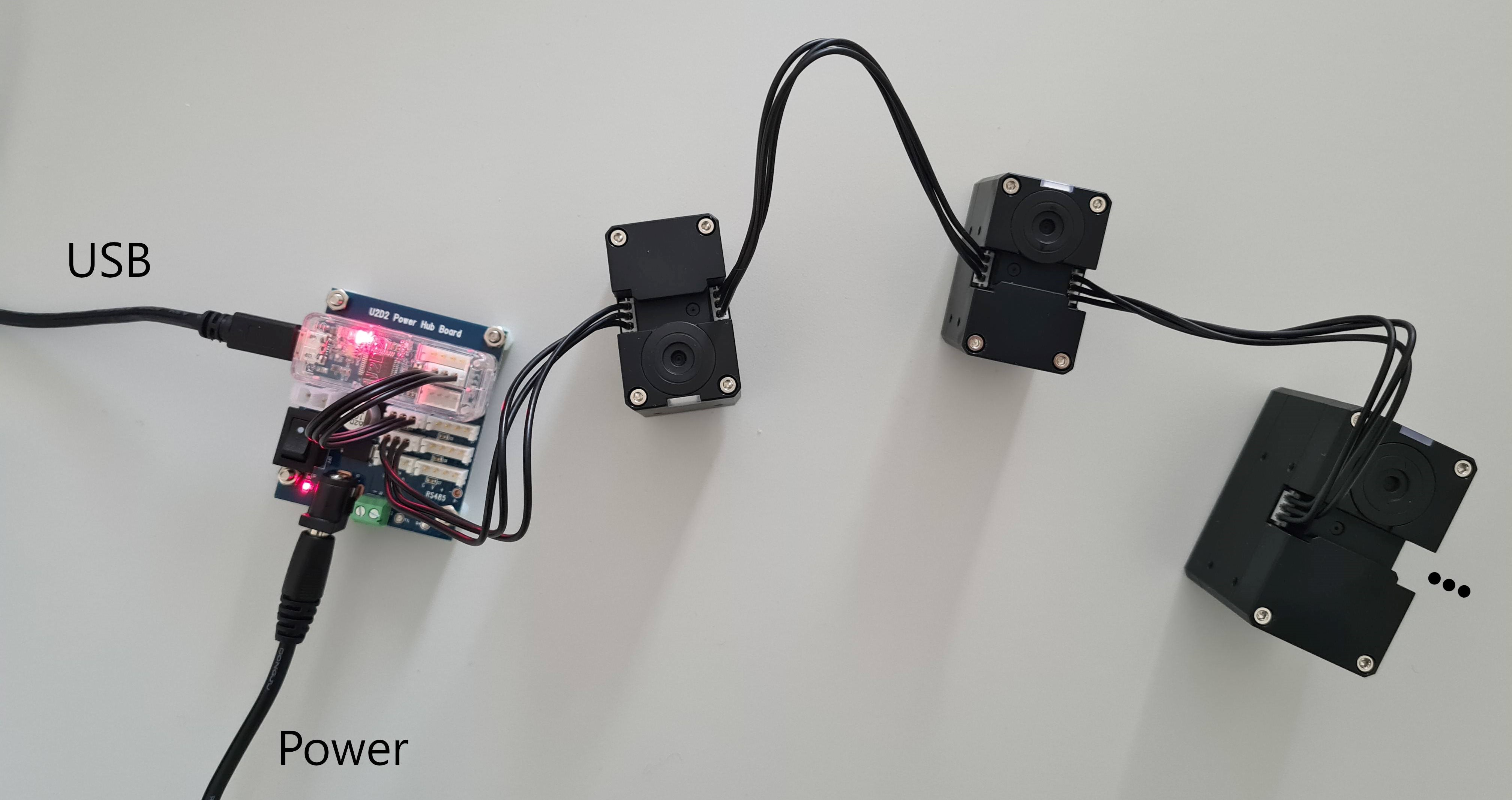 Example of a daisy chain of 3 Dynamixel motors connected to the U2D2 and the power hub.
Testing the Motors
Always make sure that the servos can turn freely before controlling them. If you try to control a servo that is blocked, it will try to reach the goal position by applying maximum torque. This can damage the servo.
Time to make the motors move! Activate the torque, either by setting control table address 64 to 1, or by clicking the “Torque” button in the sidebar. Then you can set the goal position of the motor by setting control table address 116 to a value between 0 and 4095, or you can use the control panel in the sidebar. You can test different control modes. Control modes can be switched when torque is off.
Dynamixel SDK
You can find a small example of how to send and read data to the servos in adatools/examples.
Dynamixel SDK in ROS2
To Do: Minimal example
Assembling and Mounting
Make sure to read the section How-to Assemble carefully! Make sure you use screws of correct size and length. Do not tighten screws deeper than 3mm into the side tabs on the motor.
When mounting stuff to the servo horn, make sure the screws do not touch the motor housing.
The technical drawings of the motors as well as CAD-models, can be found in the Drawings section. For importing the CAD files, download the .stp- file and upload it into your Fusion project.
Aligning zero positions of real robot and kinematic model
To control the real robot based on the kinematic model, the 0 positions and joint limits must be identical on the real robot and in the model. In position control mode, the motors operate in steps in a range from 0 to 4095 (12 bits) to cover rotations from 0 to 2pi. Thus, 0rad in the kinematic model corresponds to 2047 steps on the motor. In the kinematic model the range of the joints goes from -pi to pi to cover one full rotation. We need to map values from 0 to 4095 to -pi to pi (utils.rad2steps()). Now we can send position commands in radians to the motors. However, we must ensure that when a motor is at 0rad, the link mounted to its horn is pointing in the right direction. An easy way to achieve this is as follows:
- Send the motor to 0rad (2047steps)
- Mount the link to the horn or the horn to the axle such that the link points in the correct direction, that is, the direction the link of the kinematic model has in the spaghetti plot when it is at 0rad. For example, the second link must be horizontal when the second joint is at 0rad.
- Correct eventual small offsets with the
Homing Offsetat control table address 20 in the Dynamixel Wizard. Here you can move the zero-position of the motor in a range of -90 to 90deg (-1024 to 1024) steps.
Setting joint limits
The motors can do a full rotation in position control mode. Most likely, most of your robot’s joints will not be able to move in this full range without colliding with its own body. We must limit the motors’ range of motion, and we must consider where in our control pipeline it is clever to do so.
- We must limit the joint ranges in the kinematic model of our robot. This is crucial for using inverse kinematics for control. If we don’t limit the joints and inform the inverse kinematics solver about the limits, the solver will produce solutions (=joint angles) that our robot cannot reach without colliding with itself!
- Limit motors. After limiting our kinematic model, our solver should not produce solutions out of range, but limiting the motors itself is a very important safety measure. Being at the very end of the control pipeline, the limits defined in the motors EEPROM will serve as a safety net to catch all sorts of mistakes we have made further up in the pipeline.
- When you limit the motors, they will reject all position commands out of range. If you want the motors to move to the limit when sending an out of range command, you need to implement such a “remapping” yourself.
- Limiting the joints in Fusion can be nice but is not crucial.