Intel RealSense D435i RGB-D Camera
The Intel RealSense D435i RGB-D Camera is a depth camera that can be used to create 3D point clouds of the environment. It is used in the course to create a map of the work space and to locate objects therein.
Connecting the Camera to VM
Make sure you followed the steps for the RealSense camera under Preparing Your PC on your VM, but there are some tweaks we have to do before we can receive data from the camera. When the virtual machine is running, click on Player in the upper left corner. Go to Manage > Virtual Machine Settings. In the device list, select USB Controller and click Add. Set the USB compatibility to USB 3.1, unselect Share Bluetooth devices with the virtual machine and click OK.
Launching the Camera Node
The ROS wrapper of the Realsense SDK comes with a ready-made node that streams the camera data into the ROS network. To launch the camera node, open a terminal and run
ros2 launch realsense2_camera rs_launch.py
Check the topics on the network with
ros2 topic list
You should see a list of topics starting with /camera. You should see /camera/color/image_raw and /camera/depth/image_rect_raw. These are the topics that contain the RGB and depth images respectively. What else you see depends on the parameters you pass to the launch file.
Parameters of the Camera Node
The camera node can be configured with parameters on the ROS parameter server. You can pass parameters to the node by adding them to the launch command. For example, to launch the camera node with a resolution of 640x480 pixels, run
ros2 launch realsense2_camera rs_launch.py color_width:=640 color_height:=480
To see all available parameters on the parameter server you can use ros2 param list. While the camera node is running, you should see a long list of parameters under /camera/camera: which belong to the RealSense. To see the value of a specific parameter, use
ros2 param get /camera/camera <parameter_name>
To set the value of a parameter, use
ros2 param set /camera/camera <parameter_name> <value>
You can also use the parameter reconfigure interface in rqt to change parameters. To do so, run rqt in a terminal. In the Plugins menu, select Configuration > Dynamic Reconfigure. In the Configuration window, select /camera/camera in the sidebar menu. You should now see a list of parameters that you can change. Note that not all parameters can be changed at runtime (see overview here). If you change a parameter that cannot be changed at runtime, you have to restart the camera node. Note: In our experience the reconfigure interface for the RealSense cameras is a bit buggy and we recommend changing parameters in terminal or programmatically. 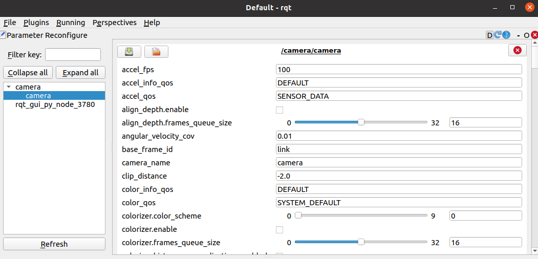
Visualizing the Camera Data in RViz
Image data are not as easily visualized in the terminal as other data types. To visualize the camera data, we use RViz. Make sure the camera node is up and running. To launch RViz, open a new terminal and run
rviz2
RGB Image
In the Displays panel, click Add, go to the By topic tab and select /camera/color/image_raw > Image. Click OK and a new panel with the RGB cameras video stream should appear.
Depth Image
In the Displays panel, click Add, go to the By topic tab and select /camera/depth/image_rect_raw > Image. Click OK and a new panel with the depth video stream should appear. The depth image represents the distance to the camera as intensities and has no colors per se. However, you can change the color map that is applied to the intensities with the colorizer parameter. Activate the colorizer by running
ros2 param set /camera/camera colorizer.enable true
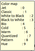
Now you choose a color map by
ros2 param set /camera/camera colorizer.color_scheme <color_map>
where <color_map> is an integer from 0 to 9.
If you are not using the colorizer, you may have to deselect Normalize Range under Image in the Displays panel and adjust the Min Value and Max value to see the depth image.
Point Cloud
In the Displays panel, click Add, go to the By topic tab and select /camera/depth/depth/color/points > PointCloud2. Click OK and a new panel with the depth video stream should appear. You probably have to changed the Fixed Frame from map to camera_link. If you do not see the “points” topic, check if you have enabled the point cloud in the camera node. To do so, check the parameter on the server with
ros2 param get /camera/camera pointcloud.enable
If the output is False, run
ros2 param set /camera/camera pointcloud.enable true
Now you should see the point cloud with the overlayed RGB colors. You can change the size of the points by changing the Size (Pixels) parameter in the PointCloud2 panel. You can also change the color of the points by changing the Color Transformer parameter.
Data Processing in ROS Node
With the camera node streaming data into the ROS network, we can now make a ROS node that subscribes to the camera topics and performs some processing on the data.
Making the Node
We are working in the project repository (2023-ada526-semester-group-project-group-< X> ) which should be located in the ros2_ws/src folder. Open a new terminal, and cd into ros2_ws/src/2023-ada526-semester-group-project-group-<X>/ros. Create a new package for your robot with a node (img_processor) for the camera processing. Think of a good name for your robot package and replace name_of_your_robot_package in the following command with your name. You will add more nodes to this package in future. Of course, you could also rename the image processing node if you want to.
ros2 pkg create --build-type ament_python --node-name img_processor name_of_your_robot_package
Now build the package. cd into ros2_ws. Then run
colcon build --symlink-install
The command above builds in fact all packages in the src folder of your workspace. If you have many packages this may take some time. You can avoid rebuilding all packages by specifying the package you want to build with the option --packages-select. For example, to build only your robot package, run
colcon build --symlink-install --packages-select name_of_your_robot_package
As always after building your ROS workspace, source the environment variables with
source ~/ros2_ws/install/setup.bash
Editing the node
Open the newly created folder of you package in VSCode and open img_processor.py. The file contains some minimal Python code that we will modify to make the node subscribe to the camera topics and process the data.
Below you see the example code for a minimal subscriber node as described in our ROS2 resources or the official ROS2 docs. This node initializes a subscriber to the topic /topic with the message type String from standard messages in ROS std_msgs.msg. It defines a callback function listener_callback which is called each time a message arrives. In this case the callback function just prints the received string to the terminal. Of course, this is just a generic example and it does not what we need.
#!/usr/bin/env python3
import rclpy
from rclpy.node import Node

from std_msgs.msg import String

class mySubscriberNode(Node):
    def __init__(self) -> None:
        super().__init__("my_subscriber")
        self.sub = self.create_subscription(
            String,
            'topic',
            self.listener_callback,
            10)
        print("Created")

    def listener_callback(self, msg):
        self.get_logger().info('I heard: "%s"' % msg.data)

def main(args=None):
    rclpy.init(args=args)
    node = mySubscriberNode()
    rclpy.spin(node)

    rclpy.shutdown()

if __name__ == '__main__':
    main()
Subscribe to RGB Image
Therefore, copy the example code into your img_processor.py file and:
- Modify the subscriber such that it subscribes to the color image topic published by the camera node. The message type of the RGB image is
Imagefromsensor_msgs.msg. - Modify the callback function such that it prints the width and height of the received image to the terminal. You can access the width and height of the image with
msg.widthandmsg.height. - Save the changes and test the node. Since we built our workspace with the option
--symlink-install, we can run the node directly without building the workspace again. Open a terminal and runros2 run name_of_your_robot_package img_processor
Add CvBridge
The image data is published as a ROS message of type Image. While this format is useful for sending images around in the ROS network, it is not handy for image processing with Python libraries such as OpenCV or the Machine Vision Toolbox (MVT). We need to convert the ROS message to an OpenCV image, which also works with MVT. For the conversion, we use the CvBridge package.
- Import the CvBridge in the top of the file
from cv_bridge import CvBridge - Create a CvBridge object in the
__init__function of the nodeself.bridge = CvBridge() - In the callback function, convert the ROS message to an OpenCV image with
cv_image = self.bridge.imgmsg_to_cv2(msg)
Add Machine Vision Toolbox And Plot Image
Now we can use the Machine Vision Toolbox (MVT) to do some plotting and image processing. The MVT is a Python toolbox for image processing and computer vision developed by Peter Corke. It is based on OpenCV and Open3D, provides a lot of useful functions but is not as overwhelming as OpenCV. We are now creating an mvt.Image object from the cv_image. This gives us access to many useful methods of the mvt.Image class. For example, we can plot an image with my_image.disp(). All details and parameters to the disp method can be found in the MVT documentation.
- Import the MVT in the top of the file
import machinevisiontoolbox as mvt - In the callback function, make an
mvt.Imagefrom the OpenCV image:img = mvt.Image(cv_image) - In the callback function, plot the image with
img.disp(reuse=True, fps=30)
We are passing two parameters to the disp method:reuse=Truewhich tells the method to reuse the same plot window for each newly arrived frame andfps=30which sets the frame rate of the plot window to 30 frames per second by making the callback function wait for \(1/30\) seconds. - Save your changes and run the node. You should see a plot window showing the RGB image stream.
Add some Image Processing
Smoothing is often a good first step to reduce noise and make the life of many image processing algorithms easier. Smoothing an image with MVT is fairly simple. We can just call the smooth method of the mvt.Image object. The smooth method takes standard deviation of the Gaussian kernel as an argument. The larger the kernel size, the more information from neighboring pixels “swaps over” and smoothing effect becomes stronger.  3x3 Gaussian kernel applied to image. The higher the standard deviation used in the kernel, the more blending with neighboring pixels takes place and the smoother the image gets. (gif from medium.com)
- In the callback function, smooth the image with
img_smoothed = img.smooth(3) - Plot the smoothed image and compare to the original.
Example Node for ‘Deprojection’
In Challenge 2 we want to move our robot to colored spheres in the workspace. We perform color blob tracking in the RGB image from the camera which gives us the pixel coordinates of the centroid of the sphere in the image. We can get the depth of the centroid from the corresponding pixel in the depth image. With the pixel coordinates and the depth (and the intrinsic parameters of the camera), we can calculate the 3D coordinates of the sphere in the camera frame (more precisely in the camera_color_optical_frame). This process is called deprojection. We use the function rs2_deproject_pixel_to_point() from the RealSense SDK for Python pyrealsense2 for this computation. You have to install the package on your VM with pip install pyrealsense2 to use the function.
Below is the example code for a ROS node doing the deprojection of a pixel in the RGB image to a 3D point in the color camera frame. The node subscribes to the RGB and depth image topics and the camera intrinsics topic. It publishes the deprojected point as a PointStamped which can be visualized in Rviz. You can use the node as a starting point for your own node for Challenge 2. You can extend the node by a adding image processing and blob detection pipeline as we discussed in the lectures.
For the node below to work properly, you must configure the real_sense camera node such that it aligns the color and depth image:
ros2 launch realsense2_camera rs_launch.py align_depth.enable:=true
Otherwise, the pixel coordinates in color and depth image will not match and the node retrieves incorrect depth values.
Example node:
import rclpy
from rclpy.node import Node

from sensor_msgs.msg import Image as image_msg
from sensor_msgs.msg import CameraInfo as camerainfo_msg
from geometry_msgs.msg import PointStamped as point_msg
from matplotlib import pyplot as plt
from cv_bridge import CvBridge
import machinevisiontoolbox as mvt
import numpy as np
import pyrealsense2 as rs

class ImageProcessor(Node):

    def __init__(self):
        super().__init__('image_processor_node')

        self.sub_intrinsics = self.create_subscription(
            camerainfo_msg,
            '/camera/aligned_depth_to_color/camera_info',
            self.sub_intrinsics_callback,
            10)

        self.sub_color = self.create_subscription(
            image_msg,
            '/camera/color/image_raw',
            self.sub_color_callback,
            10)

        self.sub_depth = self.create_subscription(
            image_msg,
            '/camera/aligned_depth_to_color/image_raw',
            self.sub_depth_callback,
            10)

        self.pub_point = self.create_publisher(
            point_msg,
            '/goal_point',
            10)

        self.br = CvBridge()
        self.fig = plt.figure(figsize=(7, 10))
        self.fig.add_subplot(2,1,1)
        self.fig.add_subplot(2,1,2)
        self.centroids = np.array([0,0])
        self.depth = 5
        self.intrinsics = rs.intrinsics()
        self.point = point_msg()


    def sub_color_callback(self, msg):
        # Convert ROS Image message to OpenCV image
        current_frame = self.br.imgmsg_to_cv2(msg)
        img = mvt.Image(current_frame)

        # -----> Image processing and pixel classification goes here <-----

        try:

            # -----> Blob detection goes here <-----

            self.centroids = [600, 350]  # replace these constant values with coordinates of the centroid of a detected blob.
            try:
                ## Deprojection: 2D pixel coordinates + depth to 3D point coordinates:
                point = rs.rs2_deproject_pixel_to_point(self.intrinsics, self.centroids, self.depth)
                #print(point)

                ## publish the point coordinates (can be visualized in rviz as a "PointStamped" message):
                self.point.header.stamp = self.get_clock().now().to_msg()
                self.point.header.frame_id = "camera_color_optical_frame"
                self.point.point.x = point[0]/1000
                self.point.point.y = point[1]/1000
                self.point.point.z = point[2]/1000
                self.pub_point.publish(self.point)
            except:
                print("Deprojecting Pixel to Point failed")
        except:
            print("No blobs found")

        ## plotting (only reccomended for debugging):
        # self.fig.axes[0].cla() # clear axis from last iteration, otherwise bounding boxes accumulate
        # self.fig.axes[0].title.set_text("Color image")
        # self.fig.axes[0].plot(self.centroids[0], self.centroids[1], 'ro')
        # img.disp(fig=self.fig, ax=self.fig.axes[0], fps=30)


    def sub_intrinsics_callback(self, msg):
        self.intrinsics.width = msg.width
        self.intrinsics.height = msg.height
        self.intrinsics.ppx = msg.k[2]
        self.intrinsics.ppy = msg.k[5]
        self.intrinsics.fx = msg.k[0]
        self.intrinsics.fy = msg.k[4]
        self.intrinsics.model = rs.distortion.none
        self.intrinsics.coeffs = [i for i in msg.d]
        #self.intrinsics.coeffs.reverse()

    def sub_depth_callback(self, msg):
        current_frame = self.br.imgmsg_to_cv2(msg)
        img = mvt.Image(current_frame)
        self.depth = img.image[int(self.centroids[1]), int(self.centroids[0])] # order of coordinates is reversed in numpy array img.image
        ## plotting (only reccomended for debugging):
        # self.fig.axes[1].cla()
        # self.fig.axes[1].title.set_text("Depth image")
        # self.fig.axes[1].plot(self.centroids[0], self.centroids[1], 'ro')
        # img.disp(fig=self.fig, ax=self.fig.axes[1], fps=30)


def main(args=None):
    rclpy.init(args=args)

    img_processor = ImageProcessor()

    rclpy.spin(img_processor)

    # Destroy the node explicitly
    # (optional - otherwise it will be done automatically
    # when the garbage collector destroys the node object)
    img_processor.destroy_node()
    rclpy.shutdown()


if __name__ == '__main__':
    main()