Mechanical Design
Designing Links
When designing the links, we should think of the different load types acting on the links. While the crossection of a link does not play any role if the link are under tension or compression, it is extremely important under bending. Bending loads are the most common load in a robot arm, and we should therefore design the links to be as stiff as possible under bending. The kinematic model of an robot arm typically does not account for bending of the links, thus any bending of the links will result in a deviation between the desired and actual end-effector position. However, we should also consider the weight of the links. The weight of the links will affect the maximum payload of the robot, and the power consumption of the motors. The weight of the links will also affect the inertia of the links, which will affect the dynamic performance of the robot. Therefore, we should not try to make the links stiff by adding more and more material, making them thick and heavy. Instead, we should try to make the links stiff by designing them with a crossection that is resistant against bending; adding some material where it is needed, and removing material where it is not needed. We try to balance the stiffness and weight of the links.
The key concept we utilize is the second moment of area, also known as the area moment of inertia. The second moment of area is a measure of the cross-sectional shape of a beam and provides insight into the beams resistance against bending due to an applied force or moment. To maximize the area moment of inertia as much as possible material should be located as far as possible away from the neutral axis. The second moment of area is a geometrical property of the cross-section, and is therefore independent of the material of the beam. The second moment of area is denoted \(I\) and has the unit \(m^4.\) This video summarizes the concept:
Structural optimization in nature
Optional
Efficiency is an evolutionary advantage. Plants competing for sunlight try to grow tall quickly, but they also need to be stiff to withstand wind and rain. It is and balancing act: using material to grow tall or using material to become stiff. Thus, a efficient plant that is as stiff as its competitors while using less material will have an advantage over its competitors. Plant stems are often hollow or U-shaped, leaves often bent or U-shaped to concentrate material far from the neutral axis to maximize the second moment of area.


Similarly, limbs of animals need to be stiff to be functional, but they should also be light to minimize energy usage. Evolution has optimized the structure of bones to be as stiff as possible while using as little material as possible. Bones are hollow; material close to the neutral axis without significant contribution to stiffness under bending is removed.
Designing Joints
Some notes on the design of the joints.
Robot Base
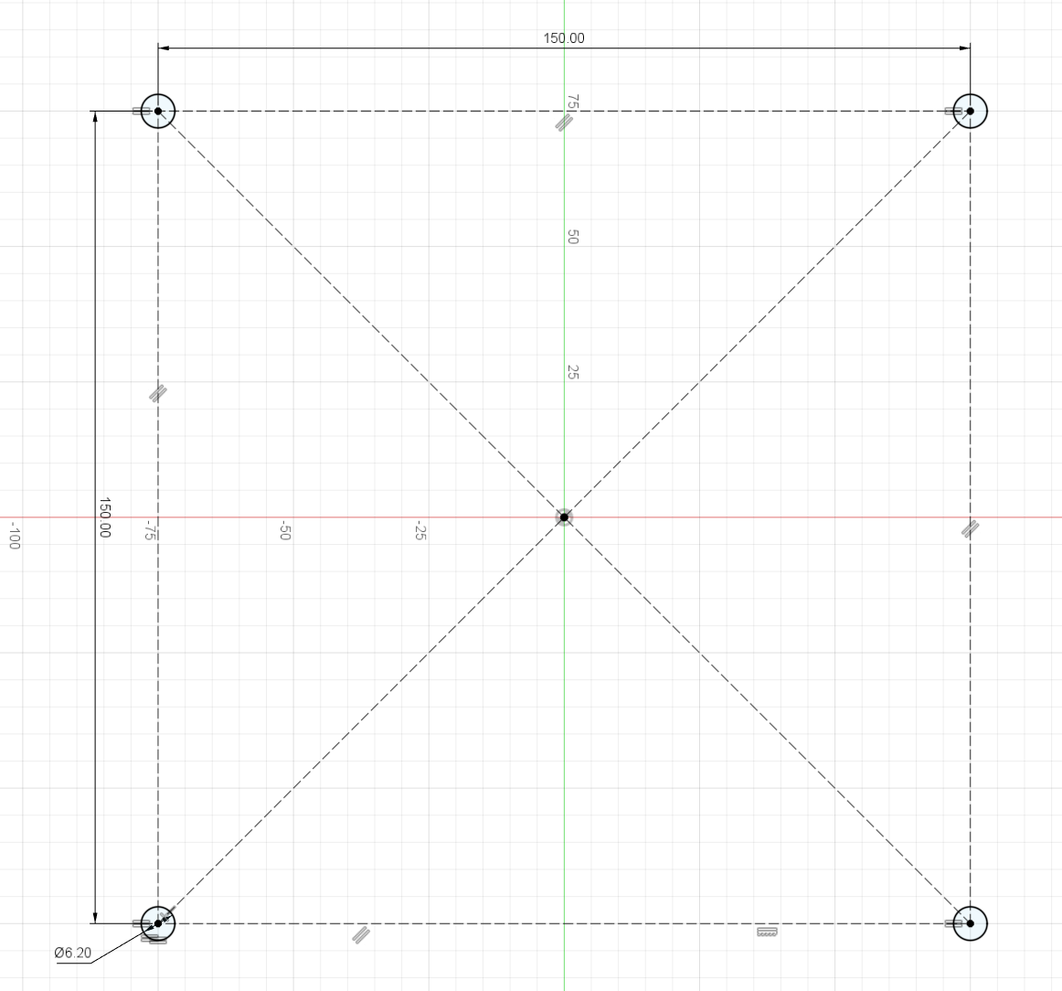
The robot base connects the standardized base plate to the first joint. It must fit the M6 mounting holes in the 150mm square pattern on the base plate. This is a design constraint that your base has to follow. The first joint motor should have its rotational axis pointing upwards in the center of this mounting square. Remember that your base can consist of multiple parts. Keep in mind that printing large flat surfaces can be challenging and often leads to warping.
Even though the base is a part of the robot that does not move, it is mechanically very important. The first joint of your robot has a vertical rotation axis, but it also has to carry the weight of the entire robot. The weight of the links, motors and payload causes high torques perpendicular to the joint axis. Therefore, you have to think carefully about how the base supports these torques. Any unwanted movement in the base joint will be amplified by the kinematic chain and result in a large deviation of the end-effector position.
For this reason, commercial robot joints usually use bearings with large diameters around the joint axis. This makes the joint stiff against tilting moments, but precision bearings in these dimensions are very expensive. This cutaway example of a commercial robotic bearing system gives an impression of how much of a robot joint can be bearing and support structure.
Common bearing choices for this type of load are slewing bearings or crossed roller bearings. Slewing bearings are characterized by wide rings, and are commonly used to support heavy but slow-turning loads with large tilting moments.
In this course, we usually have to fabricate the bearing support ourselves. See Fabricating Bearings for some approaches that are more realistic with 3D-printed parts.
Fabricating Bearings
Bearings with rollers are difficult to fabricate ourselves. 3D-printed versions exist, for example this parametric slewing bearing design, which lets you modify the dimensions to fit your design. However, it is difficult to achieve a stiff bearing that still rotates well with 3D-printed races and rollers.
Because of these manufacturing constraints, it can be more attractive to make V-groove or deep-groove style bearings with printed races and cages, but commercial steel balls, for example steel BB balls, as the rolling elements. The balls are cheap and easy to source, but they are still made with relatively high precision and good surface quality. The following videos show examples of this approach:
Mounting Dynamixel Motors
When mounting printed parts to Dynamixel motors, check the custom frame assembly section in the Dynamixel manual. The side tabs on the XM430-W350-T have M2.5 threads with a maximum depth of 3mm. Screwing anything deeper into the tabs can destroy the motor. We have M2.5 screws (DIN912) of length 8mm, 10mm and 20mm, so make sure your design fits the screws we have available.
Think also about the tolerances of the 3D printer when designing motor attachments. It is often a good idea to avoid over-constraining the motor too much, and/or to add some tolerance to the attachment instead of working with the motor’s exact dimensions. You are aiming for a snug fit, not a press fit – screws will hold the motor in place.
The technical drawings of the motors as well as CAD-models can be found in the Drawings section of the Dynamixel manuals. For importing the CAD files into Fusion, download the .stp file and upload it into your Fusion project.
XM430-W350-T Drawings XM540-W150-T Drawings
End Effector
Pen Mount
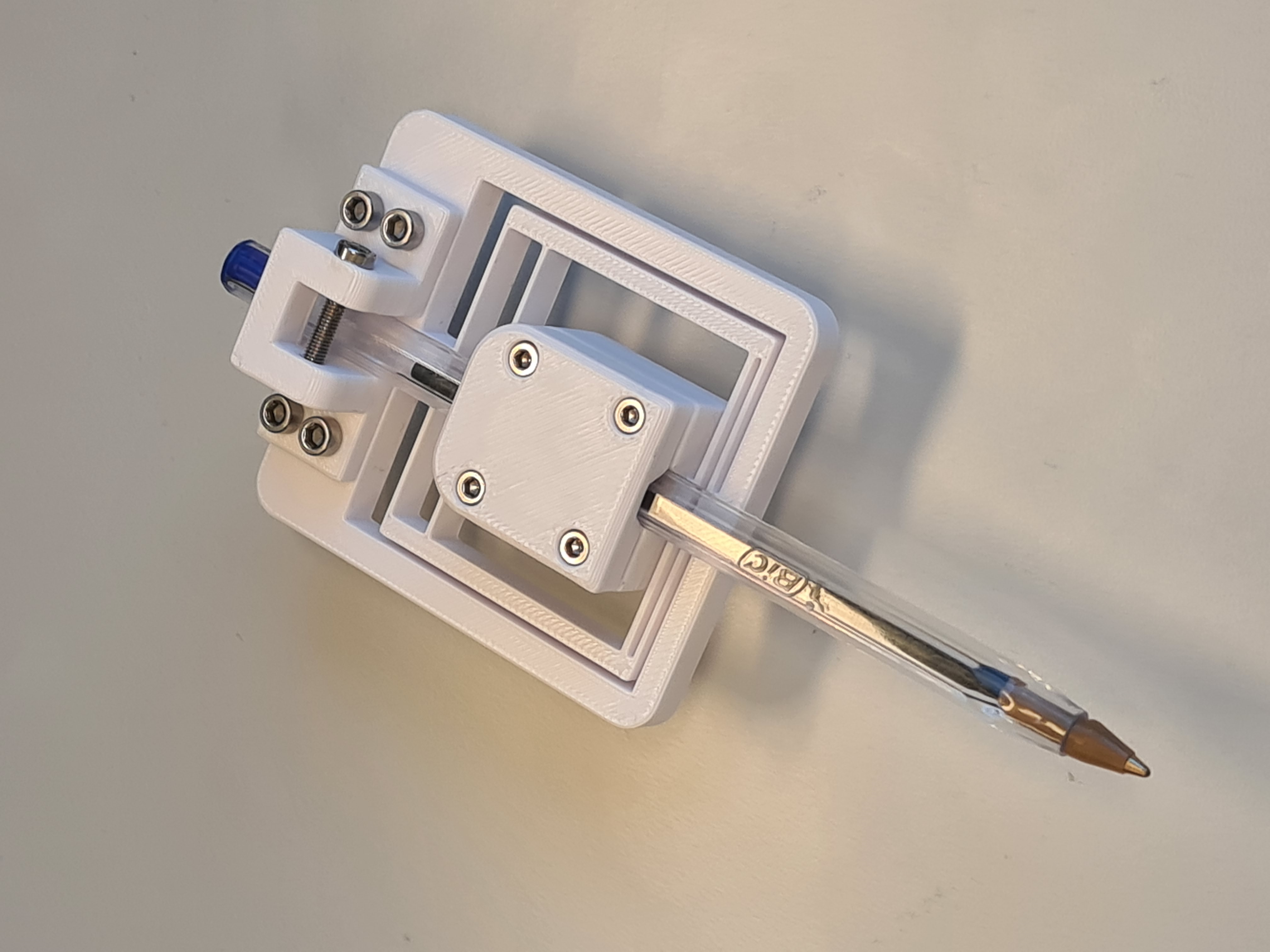
This is the pen mount we are going to use in Challenge 1. Please print it yourself and assemble it. The pen is clamped with M2.5 screws which are directly screwed into the plastic. The weight attachment requires a M3 screw across, which is also directly screwed into the plastic. The weight attachment and the pen holder are held together and mounted to your robot with four M3 screws in a 30x7mm rectangular pattern. The pen holder is designed for BIC Cristal pens.
Download Pen Mount Download BIC Cristal Pen Model