Build a Custom Robot Simulation
In this chapter we will look at how to build a gazebo simulation model of a robot given the mechanical design. If you have time to do so, we recommend you to create a CAD model of your robot before you create the simulation model as it will make this process easier. You can install Fusion 360 from Autodesk for free if you create an account with you HVL email and verify your student status. Learn Fusion 360 in 90 Minutes is recommended to get started and if you are interested in more in-depth tutarials you can find them here.
Setup Process
If you do this setup process for the lecture example make sure to use custom_robot_sim as the package name.
Before we can start defining our robot model, we have to create and configure a new ROS package:
- Open a new terminal window by pressing: Ctrl+Alt+T
- Navigate into the src folder of your ros2 workspace:
cd ~/ros2_ws/src - Create a new ROS2 python package (replace PACKAGE_NAME with the name of your package):
ros2 pkg create --build-type ament_python PACKAGE_NAME - Copy the folders launch, meshes, worlds and urdf from the ros2_students_25/custom_robot_sim git repository to your newly created package (ros2_ws/src/PACKAGE_NAME)
- In the setup.py file of your package add the following lines:
# ADD AFTER: from setuptools import setup import os from glob import glob # In order to be able to access the added files during runtime we add we add them to data_files # ADD AFTER: ('share/' + package_name, ['package.xml']), (os.path.join('share', package_name, 'launch'), glob(os.path.join('launch', '*.launch.py'))), (os.path.join('share', package_name, 'urdf'), glob(os.path.join('urdf', '*.xacro'))), (os.path.join('share', package_name, 'meshes'), glob(os.path.join('meshes', '*.stl'))), (os.path.join('share', package_name, 'worlds'), glob(os.path.join('worlds', '*.sdf'))), - Create a new file in the urdf folder of your package named
robot_description.urdf.xacro - Move to workspace directory, build your workspace and source it:
cd ~/ros2_ws colcon build --symlink-install source install/setup.bash - To launch the simulation model of the robot in gazebo run:
ros2 launch PACKAGE_NAME spawn_robot.launch.py
Basic Xacro Robot Description structure
A model of a robot in Gazebo is made of links which are connected through joints described in XML. Since this is a ROS lecture, we use URDF, a subcategory of XML, to describe the model. URDF (Unified Robot Description Format) is a description language for specifying the geometry and organization of robots in ROS. The official guides on using URDF and Xacro can be found here. In this course we will use Xacro which is a macro language for XML but has some features that can make your life easier:
- Constants: Lets you assign a value to a variable that can then be reused:
<!--Defining a constant--> <xacro:property name="width" value="0.2" /> <!--Example of how to use the defined constant--> <sphere radius="${width}"/> - Simple Math: You can build up arbitrarily complex expressions in the ${} construct using the four basic operations (+,-,*,/), the unary minus, and parenthesis. Functions and constants from the python math module (e.g.
piand trigonometric functions likesinorcos) are also available for use.<origin xyz="0.200 ${width/2} -0.050" rpy="-${pi/2} 0 0"/> - Macros: This is the main feature of xacro. Define macros with the macro tag, and specify the macro name and the list of parameters. The list of parameters should be whitespace separated. They become macro-local properties.
<!--Example of a macro definition-->
<xacro:macro name="default_inertial" params="mass">
    <inertial>
        <mass value="${mass}" />
        <inertia ixx="1e-3" ixy="0.0" ixz="0.0"
                iyy="1e-3" iyz="0.0"
                izz="1e-3" />
    </inertial>
</xacro:macro>
<!--Example of how to use the previously defined macro-->
<xacro:default_inertial mass="10"/>
To use xacro for your robot model description, the basic structure should look like this:
<?xml version="1.0" ?>

<robot name="ROBOT_NAME" xmlns:xacro="http://ros.org/wiki/xacro">
    <!-- ADD LINK AND JOINTS HERE -->
</robot>
In general it is important to notice that all distances are normally in meters and all angles in radian.
Links
Basic Structure
The official documentation on how to define a link in URDF can be found here.
<link name="LINK_NAME">
    <visual>
        <origin xyz="0 0 0" rpy="0 0 0"/>
        <geometry>
            <!-- ADD VISUAL GEOMETRY HERE -->
        </geometry>
    </visual>
    <collision>
        <origin xyz="0 0 0" rpy="0 0 0"/>
        <geometry>
            <!-- ADD COLLISION GEOMETRY HERE -->
        </geometry>
    </collision>
    <inertial>
        <!-- ADD INERTIAL PARAMETERS HERE -->
    </inertial>
</link>
Dummy Links
It is good practice to define the first link of your robot definition as an empty link/dummy link which you then connect your robots’ base link to with a fixed joint. You can find more information on why we do this here.
<link name="LINK_NAME"/>
Geometries
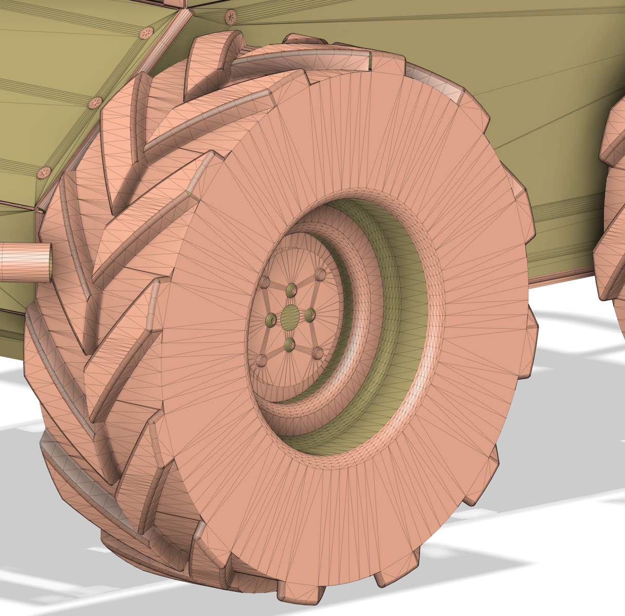
The geometry defines the shape of the visual object. This can be a simple shape (box, cylinder or sphere) or a mesh geometry. A mesh uses a combination of triangles to create shapes that are not simple shapes. The more complex the geometry and the higher the resolution the more triangles are needed:
Box
<!--size parameters: length_along_x_axis length_along_y_axis length_along_z_axis-->
<box size="0.0 0.0 0.0"/>
Cylinder
<cylinder length="0.0" radius="0.0" />
Sphere
<sphere radius="0.0"/>
Mesh
<mesh filename="$(find PACKAGE_NAME)/meshes/MESH_FILENAME.stl" />
Inertial Parameters
An accurate simulation requires accurate dynamic properties of the links. These are defined by the inertial parameters. An official guide on the those parameters can be found here. There are multiple ways of calculating these parameters. Here are some options:
- If you designed you robot model in a CAD software you can often read out these parameters for your model. In Autodesk Fusion 360 you can assign a material to your model and then read out the physical properties.
- The online tool mesh cleaner to calculate the inertial parameters for mesh files automatically can be found here. Note that this doesn’t always work and depends on how complex your shapes are.
- An approximation can also be made by calculating the inertial parameters for a simple shape that is close to the model. You can use the following macros for that. The list of the formulas used in these macros to calculate the inertial parameters can be found here.
Make sure the center of mass is in the accurate location. For simple shapes it is in the center of the link, which means, as long as the
<inertial>
    <origin xyz="0 0 0" rpy="0 0 0"/>
    <mass value="1.0"/>
    <inertia
        ixx="1.0" ixy="0.0" ixz="0.0"
        iyy="1.0" iyz="0.0"
        izz="1.0"/>
</inertial>
Box Macro Usage
<xacro:inertial_box length="0.0" width="0.0" height="0.0" density="1">
    <origin xyz="0 0 0" rpy="0 0 0"/>
</xacro:inertial_box>
Cylinder Macro Usage
<xacro:inertial_cylinder length="0.0" radius="0.0" density="1">
    <origin xyz="0 0 0" rpy="0 0 0"/>
</xacro:inertial_cylinder>
Sphere Macro Usage
<xacro:inertial_cylinder radius="0.0" density="1">
    <origin xyz="0 0 0" rpy="0 0 0"/>
</xacro:inertial_cylinder>
Joints
The official documentation of how to define a joint in urdf can be found here. Some important parts of the joint definition are the following:
<axis>defines which axis is used by the joint for movement.<limit>effortmaximum torque/force measured in [Nm]velocitymaximum speed measured in [m/s] for primatic joints and [rad/s] for revolute jointslowerminimum allowed joint angle/position measured in [m] for prismatic joints and [rad] for revolute joints.uppermaximum allowed joint angle/position
Revolute Joint
Revolute joints also rotate around the defined axis (1 degree of freedom) and have a defined minimum and maximum joint angle in [rad].
<joint type="revolute" name="JOINT_NAME">
    <origin xyz="0.0 0.0 0.0" rpy="0.0 0.0 0.0"/>
    <child link="CHILD_LINK_NAME"/>
    <parent link="PARENT_LINK_NAME"/>
    <axis xyz="0 0 1" rpy="0 0 0"/>
    <limit effort="100" velocity="100" lower="-${pi/2}" upper="${pi/2}"/>
    <dynamics damping="0.7" friction="1.0"/>
</joint>
Prismatic Joint
Prismatic joints move along the defined axis (1 degree of freedom) and have a minimum and maximum joint position defined in [m].
<joint type="prismatic" name="JOINT_NAME">
    <origin xyz="0 0 1.0" rpy="0 0 0"/>
    <child link="CHILD_LINK_NAME"/>
    <parent link="PARENT_LINK_NAME"/>
    <axis xyz="0 0 1" rpy="0 0 0"/>
    <limit effort="100" velocity="100" lower="-1.0" upper="1.0"/>
    <dynamics damping="0.7" friction="1.0"/>
</joint>
Fixed Joint
Fixed joints are not really joints because all degrees of freedom are blocked.
<joint type="fixed" name="JOINT_NAME">
    <parent link="PARENT_LINK_NAME"/>
    <child link="CHILD_LINK_NAME" />
    <origin xyz="0 0 0" rpy="0 0 0"/>
</joint>
Mimic Joint
You can find the official ros2_control documentation about it here. Sometimes it can be convenient to just make one joint mimic the movement of another. An example of this would be a two-finger gripper where both finger joint should always move together. We can do this by adding a mimic parameter in the URDF definition of a joint. The mimic tag looks like this:
<mimic joint="JOINT_NAME" multiplier="1" offset="0"/>
An example of two prismatic joints of the gripper where one mimics the movement of the other can be seen here:
<joint type="prismatic" name="gripper_finger_left_joint">
    <origin xyz="0.0 0.0 0.0" rpy="0 0 0"/>
    <child link="gripper_finger_left_link"/>
    <parent link="gripper_base_link"/>
    <axis xyz="0 0 1" rpy="0 0 0"/>
    <limit effort="100" velocity="100" lower="-1.0" upper="1.0"/>
    <dynamics damping="0.7" friction="1.0"/>
</joint>

<joint type="prismatic" name="gripper_finger_right_joint">
    <mimic joint="gripper_finger_left_joint" multiplier="1" offset="0"/>
    <origin xyz="0.0 0.0 0.0" rpy="0 0 0"/>
    <child link="gripper_finger_right_link"/>
    <parent link="gripper_base_link"/>
    <axis xyz="0 0 1" rpy="0 0 0"/>
    <limit effort="100" velocity="100" lower="-1.0" upper="1.0"/>
    <dynamics damping="0.7" friction="1.0"/>
</joint>
The value of the mimic joint can be computed as value = multiplier * other_joint_value + offset. It is important to note that the standard physics engine of gazebo does not support this feature. Therefore we have to change the physics engine when launching gazebo by adding the launch argument --physics-engine gz-physics-bullet-featherstone-plugin. Here is the full launch file code:
gazebo_sim = IncludeLaunchDescription(
    PythonLaunchDescriptionSource(
        os.path.join(get_package_share_directory('ros_gz_sim'), 'launch', 'gz_sim.launch.py')
    ),
    launch_arguments={'gz_args': '-r ' + world_file +' --physics-engine gz-physics-bullet-featherstone-plugin'}.items()
)
Materials
Changing the color of the visual element of a link can be done by defining and using materials. A example material definition looks like this:
<material name="blue">
    <color rgba="0 0 0.8 1"/>
</material>
The material can then be used in the link definition like this:
<visual>
    <origin xyz="0 0 0" rpy="0 0 0"/>
    <geometry>
        <!-- Geometry definition -->
    </geometry>
    <material name="blue"/>
</visual>
Include other xacro files
<xacro:include filename="$(find PACKAGE_NAME)/urdf/FILENAME.xacro" />
Exercise
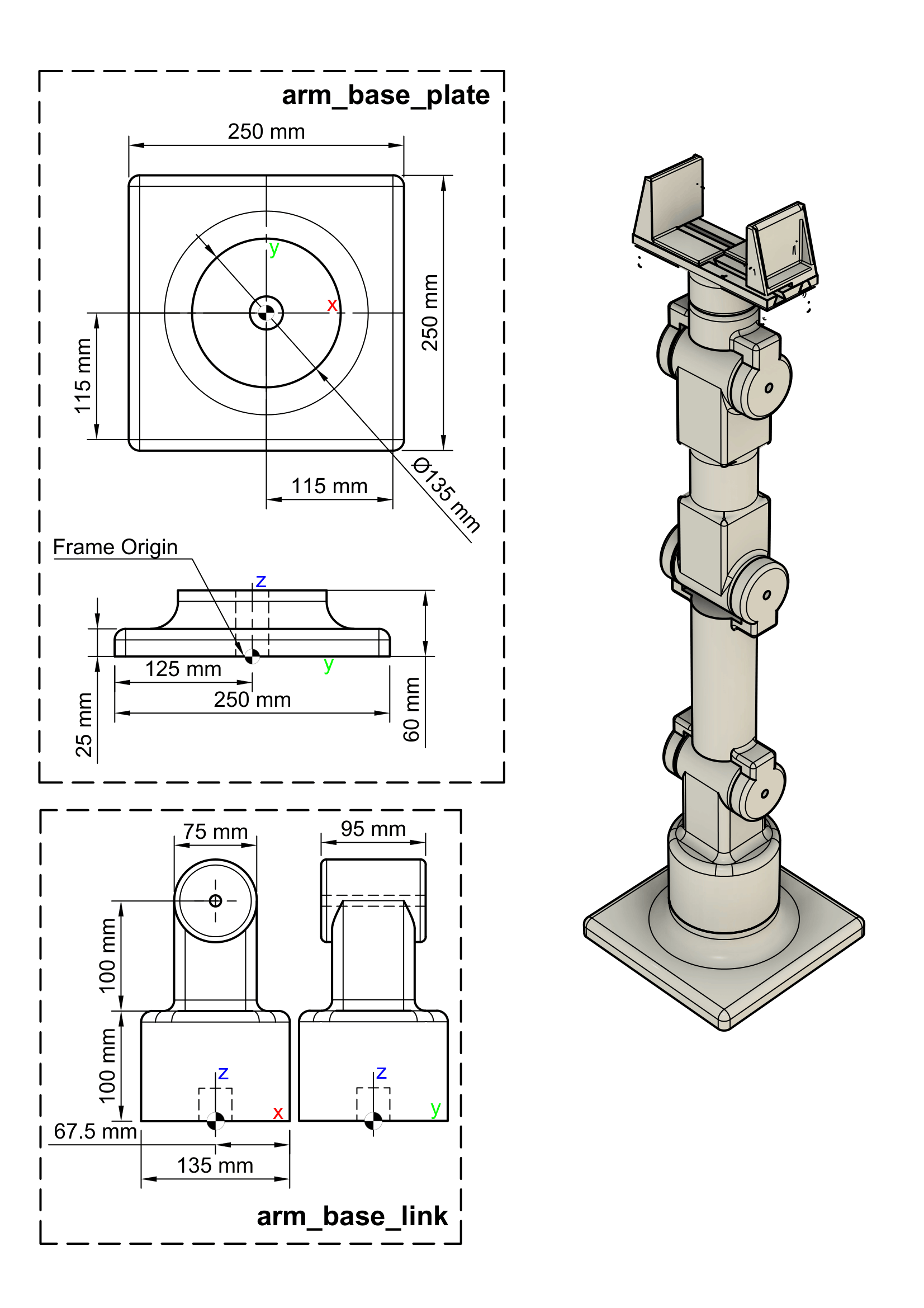
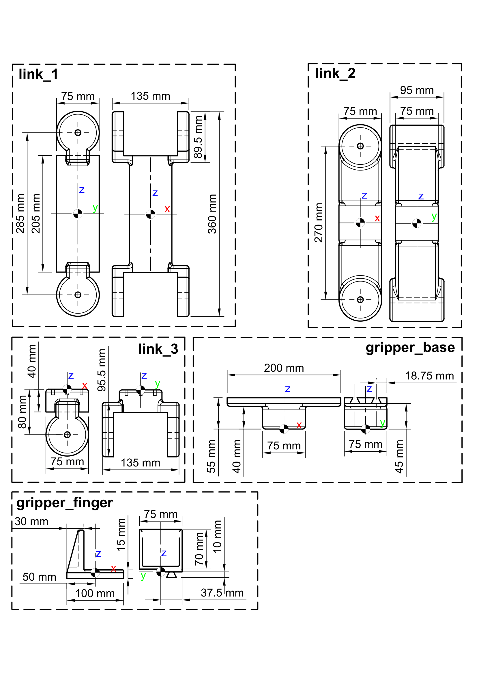
For the exercise you are given the robot description of the base and the first two joints with their connected links. Your job is to add the remaining joints and links of the robot, including the gripper. Use the mechanical drawing of the robot for the right placements. Before starting the exercises make sure you have gone through the setup process in the beginning of this page. Copy the exercise code into the robot_description.urdf.xacro file that you created.
Mechanical Drawing
Exercise Code
<?xml version="1.0" ?>

<robot name="custom_manipulator" xmlns:xacro="http://ros.org/wiki/xacro">
    <xacro:include filename="$(find custom_robot_sim)/urdf/inertial_macros.urdf.xacro" />

    <xacro:property name="pla_density" value="600" />

    <material name="blue">
        <color rgba="0 0 0.8 0.5"/>
    </material>


    <link name="base_footprint"/>

    <joint name="footprint_joint" type="fixed">
        <parent link="base_footprint"/>
        <child link="arm_base_plate" />
        <origin xyz="0 0 0" rpy="0 0 0"/>
    </joint>

    <!--############################### -->
    <!-- ARM BASE PLATE -->
    <!--############################### -->

    <link name="arm_base_plate">
        <visual>
            <origin xyz="0 0 0" rpy="0 0 0"/>
            <geometry>
                <mesh filename="$(find custom_robot_sim)/meshes/arm_base_plate.stl" />
            </geometry>
            <material name="blue"/>
        </visual>
        <collision>
            <origin xyz="0 0 ${0.025/2}" rpy="0 0 0"/>
            <geometry>
                <box size="0.25 0.25 0.025"/>
            </geometry>
        </collision>
        <collision>
            <origin xyz="0 0 ${0.025+0.035/2}" rpy="0 0 0"/>
            <geometry>
                <cylinder length="0.035" radius="${0.135/2}" />
            </geometry>
        </collision>
        <xacro:inertial_box length="0.25" width="0.25" height="0.06" density="${pla_density}">
            <origin xyz="0 0 0.03" rpy="0 0 0"/>
        </xacro:inertial_box>
    </link>

    <!--############################### -->
    <!-- ARM BASE -->
    <!--############################### -->

    <joint type="revolute" name="arm_base_joint">
        <origin xyz="0.0 0.0 0.06" rpy="0.0 0.0 0.0"/>
        <child link="arm_base_link"/>
        <parent link="arm_base_plate"/>
        <axis xyz="0 0 1" rpy="0 0 0"/>
        <limit effort="100" velocity="100" lower="-${pi}" upper="${pi}"/>
        <dynamics damping="0.7" friction="1.0"/>
    </joint>

    <link name="arm_base_link">
        <visual>
            <origin xyz="0 0 0" rpy="0 0 0"/>
            <geometry>
                <mesh filename="$(find custom_robot_sim)/meshes/arm_base_link.stl" />
            </geometry>
            <material name="blue"/>
        </visual>
        <collision>
            <origin xyz="0 0 ${0.1/2}" rpy="0 0 0"/>
            <geometry>
                <cylinder length="0.1" radius="${0.135/2}" />
            </geometry>
        </collision>
        <collision>
            <origin xyz="0 0 0.15" rpy="0 0 0"/>
            <geometry>
                <box size="0.075 0.075 0.1" />
            </geometry>
        </collision>
        <xacro:inertial_cylinder radius="${0.135/2}" length="0.2" density="${pla_density}">
            <origin xyz="0 0 0.1" rpy="0 0 0"/>
        </xacro:inertial_cylinder>
    </link>

    <!--############################### -->
    <!-- LINK 1 -->
    <!--############################### -->
    <joint type="revolute" name="link_1_joint">
        <origin xyz="0.0 0.0 0.2" rpy="${-pi/2} 0.0 0.0"/>
        <child link="link_1_link"/>
        <parent link="arm_base_link"/>
        <axis xyz="0 0 1" rpy="0 0 0"/>
        <limit effort="100" velocity="100" lower="-${pi/2}" upper="${pi/2}"/>
        <dynamics damping="0.7" friction="1.0"/>
    </joint>

    <link name="link_1_link">
        <visual>
            <origin xyz="0 -${0.285/2} 0" rpy="${pi/2} 0 0"/>
            <geometry>
                <mesh filename="$(find custom_robot_sim)/meshes/link_1.stl" />
            </geometry>
            <material name="blue"/>
        </visual>
        <collision>
            <origin xyz="0 -${(0.0895-0.075)/2} 0" rpy="0 0 0"/>
            <geometry>
                <cylinder length="0.135" radius="${0.0895/2}" />
            </geometry>
        </collision>
        <collision>
            <origin xyz="0 -${0.285/2} 0" rpy="${pi/2} 0 0"/>
            <geometry>
                <cylinder length="0.205" radius="${0.075/2}" />
            </geometry>
        </collision>
        <collision>
            <origin xyz="0 -${0.285-(0.0895-0.075)/2} 0" rpy="0 0 0"/>
            <geometry>
                <cylinder length="0.135" radius="${0.0895/2}" />
            </geometry>
        </collision>
        <xacro:inertial_cylinder radius="${0.075/2}" length="0.205" density="${pla_density}">
            <origin xyz="0 -${0.285/2} 0" rpy="${pi/2} 0 0"/>
        </xacro:inertial_cylinder>
    </link>


    <!--############################### -->
    <!-- LINK 2 -->
    <!--############################### -->


    <!--############################### -->
    <!-- LINK 3 -->
    <!--############################### -->


    <!--############################### -->
    <!-- GRIPPER BASE -->
    <!--############################### -->


    <!--############################### -->
    <!-- GRIPPER FINGER LEFT -->
    <!--############################### -->


    <!--############################### -->
    <!-- GRIPPER FINGER RIGHT -->
    <!--############################### -->


</robot>